
Ohm's law lab: measure V and I and find R
- Objective
- Measure the voltage across a resistor and the current through it at several settings, plot V against I, and use the slope of the graph to find the resistance.
- Level
- Middle and high school
- Time
- 40 minutes
- Topics
- Ohm's law, voltage, current, resistance, V-I graphs
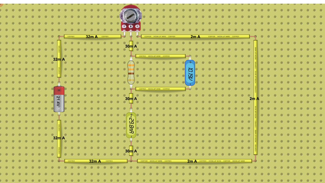
Steps
- Look at the circuit: a 21.4 V battery feeds a 5 kΩ potentiometer, and the potentiometer sets the voltage across a 341.88 Ω resistor. Two small meters sit in the loop: the A meter (ammeter), in series below the resistor, shows the current through it, and the V meter (voltmeter), across the resistor, shows the voltage across it.
- Press Open in the lab. The copy on this page pauses after two minutes; the lab keeps running.
- Read both displays before you touch anything and write the values in the first row of the table (V in volts, I in amperes).
- Turn the potentiometer knob a little, wait for the readings to settle and record V and I again. Take at least six readings, from about 1 V up to the highest voltage the knob gives.
- For every row, work out V ÷ I and P = V × I and write them in the table.
- Plot V on the vertical axis against I on the horizontal axis, draw the best straight line through your points and find its slope.
- Click the resistor, change its resistance in the property panel to 680 Ω and take three more readings. Compare them with the first set.
Data table
| Reading | Voltage V (V) | Current I (A) | V ÷ I (Ω) | Power P = V × I (W) |
|---|---|---|---|---|
Questions
- What value of V ÷ I did you get in each row? What does that tell you about the resistor?
- Describe your V-I graph. What is its slope, and does the line pass through the origin?
- At the starting position the voltmeter reads about 10.2 V. Use Ohm's law to predict the current, then compare your answer with the A meter.
- What is the largest current through the resistor when the knob gives the full 21.4 V of the battery?
- How much power does the resistor turn into heat at 10.2 V, and at 21.4 V? Would a real 1/4 W resistor be safe here?
- Compare your three readings at 680 Ω with the first set. What happened to the current at about the same voltage, and to the slope of the V-I line?
For teachers
Answer key
- About 342 Ω in every row (the resistor is 341.88 Ω). The ratio stays the same while V and I change, so the current is proportional to the voltage: the resistor obeys Ohm's law. Small differences come from rounding the displays.
- A straight line through the origin. With V on the vertical axis the slope is ΔV ÷ ΔI ≈ 342 Ω, the resistance.
- I = V ÷ R = 10.2 V ÷ 341.88 Ω ≈ 0.0298 A (29.8 mA). The A meter shows about 29.8 mA (0.0298 A), so the prediction matches.
- I = 21.4 V ÷ 341.88 Ω ≈ 0.0626 A (62.6 mA).
- At 10.2 V: P = V × I = 10.2 V × 0.0298 A ≈ 0.30 W. At 21.4 V: P = V² ÷ R = (21.4 V)² ÷ 341.88 Ω ≈ 1.34 W. Both are above 0.25 W, so a 1/4 W resistor would overheat; it would need a rating of at least 2 W.
- 680 Ω is about twice 342 Ω, so at the same voltage the current is about half (I = V ÷ R), and the V-I line is about twice as steep: a slope of about 680 Ω.
Frequently asked questions
Can students do this at home?
Yes. The lab runs in a web browser, and anyone can open this public circuit, run it and change its values without signing in. The copy on this page pauses after two minutes; Open in the lab keeps it running.
Do students need an account?
Not to run the circuit and take readings. They need a free account to save their own copy, and to hand the work in as an assignment they join your class through its join link.
Why use a potentiometer instead of changing the battery?
One knob gives a whole range of voltages, from 0 V up to the battery's 21.4 V, so students can take many readings in a few minutes without rewiring the circuit.
Teaching with circuits?
Create a classroom, give your students this lab, and review what they submit. The free classroom demo gives you one classroom with room for 30 students for 7 days, counted from when your first student joins (once per teacher); after that it keeps up to 5 students.
Try the free classroom demo