
Half-wave rectifier lab: from AC to DC with a filter capacitor
- Objective
- See how one diode turns AC into pulsing DC, measure the peak and average output, and show how a filter capacitor smooths the output and what it does to the ripple and to the diode.
- Level
- High school and first-year college
- Time
- 50 minutes
- Topics
- Rectification, half-wave rectifier, diodes, filter capacitor, ripple voltage, peak inverse voltage
Steps
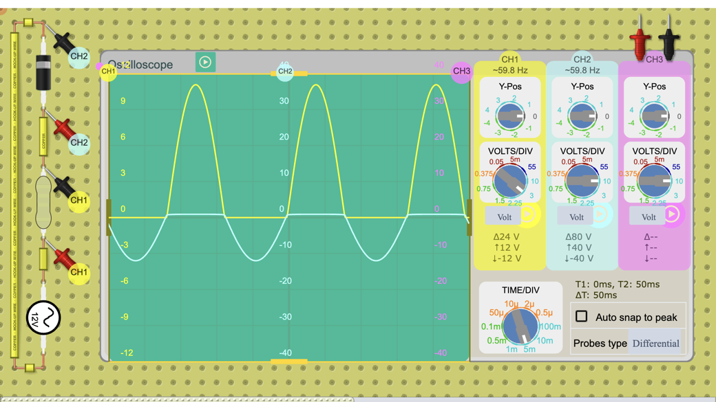
- Look at the circuit: a column on the left of the board with a diode at the top, then a 1 Ω load resistor, then a 12 V peak, 60 Hz AC source at the bottom. The oscilloscope is on the right: channel 1 is across the load (3 V/div) and channel 2 across the diode (10 V/div, positive when it conducts), at 5 ms/div.
- Press Open in the lab; the oscilloscope is already set up. Sketch what you see and read the peak: about 11 V across the 1 Ω load, so the current peaks at about 11 A.
- Click the load resistor and set its resistance to 1 kΩ. Read the new peak voltage and work out the diode's voltage drop (12 V minus the peak).
- Estimate the DC (average) value of the output with V_avg ≈ V_peak ÷ π and record it.
- From the toolbar, add a plain Capacitor (not the polarized one) across the load resistor and set it to 1000 µF. Read the highest and the lowest output voltage and work out the ripple (highest minus lowest).
- Change the capacitor to 100 µF and watch the ripple. Then set it back to 1000 µF.
- Channel 2 already shows the diode voltage: read its most negative value, with and without the capacitor.
Data table
| Load (Ω) | Filter capacitor (µF) | Peak voltage (V) | Lowest voltage (V) | Ripple (V) | Diode reverse peak (V) |
|---|---|---|---|---|---|
Questions
- Without the capacitor, what does the output look like, and why are the negative halves missing?
- With the 1 kΩ load, what is the peak output voltage and the diode's voltage drop? Why was the peak lower with the 1 Ω load?
- What is the DC (average) value of the half-wave output with the 1 kΩ load and no capacitor?
- With the 1000 µF capacitor, what ripple did you measure? Compare it with the estimate ΔV ≈ V_peak ÷ (f × R × C).
- What happened to the ripple with 100 µF? Name two ways to make the ripple smaller.
- Why does the diode's reverse voltage grow when the capacitor is added, and why does that matter when you choose a diode?
For teachers
Answer key
- Only the positive halves of the sine wave appear, as separate humps with flat 0 V gaps between them: pulsing DC. On the negative half the diode is reverse-biased and blocks, so no current reaches the load.
- About 11.4 V, so the diode drops about 0.6 V (12 V − 11.4 V; the simulator gives about 0.57 V). With the 1 Ω load the current peaks at about 11 A, and the diode drops more at that current (about 0.93 V), so the peak was only about 11 V.
- V_avg ≈ V_peak ÷ π = 11.4 V ÷ 3.14 ≈ 3.6 V.
- The output stays between about 11.13 V and 11.30 V: a ripple of about 0.17 V. The estimate gives 11.4 V ÷ (60 Hz × 1000 Ω × 0.001 F) = 0.19 V. The formula assumes the capacitor discharges for a whole cycle, so it slightly overestimates.
- It grows about ten times: the formula gives roughly 1.9 V (the simulator may read a little less, as it did with 1000 µF). A bigger capacitor or a larger load resistance (a smaller load current) makes the ripple smaller; a full-wave rectifier, which doubles the ripple frequency, also helps.
- The capacitor holds the output near +11.3 V while the source swings to −12 V, so the diode sees both: about −23.2 V, nearly twice the peak. Without the capacitor it sees only about −12 V. The diode's peak inverse voltage rating must be higher than this.
Frequently asked questions
Can students do this at home?
Yes. The lab runs in a web browser, and anyone can open this public circuit, run it and change it without signing in. The copy on this page pauses after two minutes; Open in the lab keeps it running.
Do students need an account?
Not to run the circuit and read the oscilloscope. They need a free account to save their own copy, and to hand the work in as an assignment they join your class through its join link.
What should students know before this lab?
That a diode conducts in one direction only, and how to read peak voltage and time on an oscilloscope. The diode forward and reverse bias lab covers the first part.
Teaching with circuits?
Create a classroom, give your students this lab, and review what they submit. The free classroom demo gives you one classroom with room for 30 students for 7 days, counted from when your first student joins (once per teacher); after that it keeps up to 5 students.
Try the free classroom demo