
LED and resistor lab: choose a current-limiting resistor
- Objective
- Measure how one series resistor sets the current through a red LED, use R = (Vs − Vf) ÷ I to choose a resistor for at most 20 mA, and see what happens when the current goes above the LED's limit.
- Level
- Middle and high school
- Time
- 40 minutes
- Topics
- LEDs, current-limiting resistor, forward voltage, Ohm's law, power
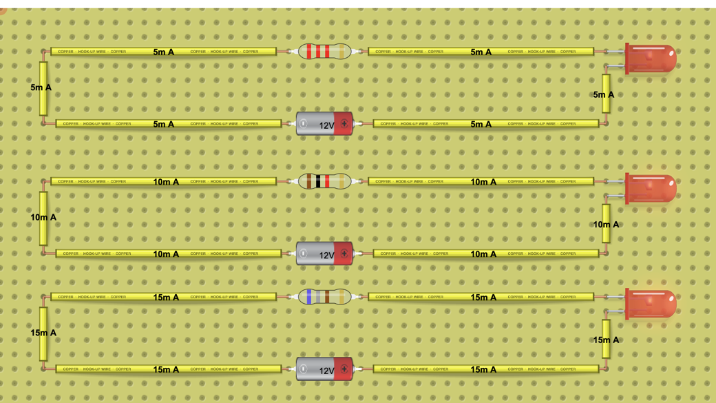
Steps
- Look at the circuit: three rows, each with a 12 V battery, one resistor and a red LED. The resistors are 2.2 kΩ (row 1), 1 kΩ (row 2) and 680 Ω (row 3). As with a real part, the red LED in the simulator takes 20 mA at most and burns out a few seconds after the current goes above that.
- Press Open in the lab and compare the brightness of the three LEDs.
- Add a digital multimeter. On DC voltage, 20 V range, measure the voltage across each LED and across each resistor.
- Find the current in each row: click a wire and tick Show Ampere, or divide the resistor's voltage by its resistance. Record it in mA.
- Calculate the resistor that would give 20 mA from 12 V: R = (Vs − Vf) ÷ I, with the LED voltage you measured. Decide which standard resistor value you would use.
- Click row 3's resistor, set it to the standard value you chose, and measure the current and the LED voltage again.
- Now set row 3's resistor to 470 Ω, measure the current and watch the LED for a few seconds. Reload the page to get the original circuit back.
Data table
| Row / resistor | Resistance (Ω) | LED voltage (V) | Resistor voltage (V) | Current (mA) | LED state (lit, brightness, burned out) |
|---|---|---|---|---|---|
Questions
- How does the current change as the resistor goes from 2.2 kΩ to 1 kΩ to 680 Ω? How does the brightness change?
- The current more than triples from row 1 to row 3. Why does the LED voltage barely change, and where does the rest of the 12 V go?
- What resistor gives 20 mA through the red LED from 12 V? Which standard value did you choose, and what current did you measure with it?
- What happened at 470 Ω? Why do you round the resistor up to the next standard value rather than down?
- How much power does row 3's resistor turn into heat at 680 Ω and at the value you chose? Is a 1/4 W resistor enough?
- What would happen if the LED were connected straight to the 12 V battery with no resistor?
For teachers
Answer key
- About 4.76 mA, 10.44 mA and 15.32 mA, and the LEDs get brighter from row 1 to row 3. The resistor voltage stays near 10.4 V, so I = (12 V − V_LED) ÷ R is roughly inversely proportional to R: going from 2.2 kΩ to 1 kΩ divides the resistance by 2.2 and multiplies the current by about 2.2.
- An LED's current rises very steeply with its voltage, so a small change in voltage covers a big change in current: here 1.52 V to 1.58 V while the current goes from 4.76 mA to 15.32 mA. The resistor takes the rest, about 10.4-10.5 V, so the resistor is what sets the current.
- R = (12 V − 1.6 V) ÷ 0.020 A = 520 Ω. That is not a standard value, so use the next one up, 560 Ω: I = (12 V − 1.6 V) ÷ 560 Ω ≈ 18.6 mA. The simulator reads about 19 mA (19.06 mA, LED 1.60 V), a little higher because its resistors model a 5% tolerance band when you change them, so about 18.6-19 mA is right.
- The current rose to about 22 mA (22.1-22.7 mA), above the LED's 20 mA maximum, and the LED burned out within a few seconds; (12 V − 1.6 V) ÷ 470 Ω ≈ 22 mA predicts it. Rounding up keeps the current at or below the limit, and the LED is only slightly dimmer.
- At 680 Ω: P = I² × R = (0.01532 A)² × 680 Ω ≈ 0.16 W. At 560 Ω: P = (0.0186 A)² × 560 Ω ≈ 0.19 W. Both are below 0.25 W, so a 1/4 W resistor is enough.
- Nothing but the LED and the battery's small internal resistance would limit the current. Because an LED's current rises very steeply above its forward voltage, the current would shoot far past 20 mA and the LED would burn out, in the simulator as in a real circuit.
Frequently asked questions
Can students do this at home?
Yes. The lab runs in a web browser, and anyone can open this public circuit, run it and change its values without signing in. The copy on this page pauses after two minutes; Open in the lab keeps it running.
Do students need an account?
Not to run the circuit and take measurements. They need a free account to save their own copy, and to hand the work in as an assignment they join your class through its join link.
Is 20 mA the right current for every LED?
No. Use the current on the LED's datasheet. 20 mA is typical for a standard 5 mm indicator LED, and many modern LEDs are bright enough at 5-10 mA. The same formula, R = (Vs − Vf) ÷ I, works for any target.
Teaching with circuits?
Create a classroom, give your students this lab, and review what they submit. The free classroom demo gives you one classroom with room for 30 students for 7 days, counted from when your first student joins (once per teacher); after that it keeps up to 5 students.
Try the free classroom demo