
Diode lab: forward bias, reverse bias and the I-V curve
- Objective
- Show that a diode conducts in one direction only, measure its forward voltage and its reverse voltage, and sketch its current-voltage (I-V) curve.
- Level
- High school and first-year college
- Time
- 45 minutes
- Topics
- Diodes, forward bias, reverse bias, forward voltage, I-V curve
Steps
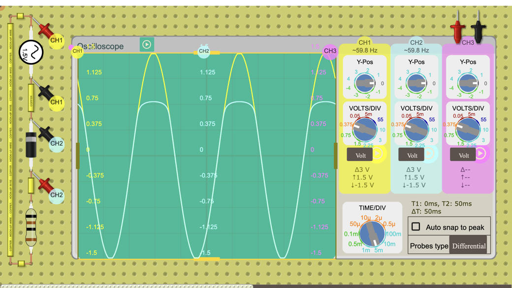
- Look at the circuit: a 1.5 V peak, 60 Hz AC source drives a silicon diode in series with a resistor of about 1 Ω (0.998 Ω). The circuit is a column on the left of the board (the source at the top, then the diode, then the resistor) and the oscilloscope is on the right: channel 1 shows the source voltage and channel 2 the voltage across the diode, positive when it conducts. Both channels are preset to 0.375 V/div and 5 ms/div, so 2-3 cycles fit on the screen.
- Press Open in the lab and let the circuit run. The oscilloscope is already set up; you can change VOLTS/DIV if you want a closer look.
- Forward bias: on the positive half of each cycle the diode conducts. Read the diode voltage at the peak on channel 2 and the source peak on channel 1, and record both.
- Work out the peak current: I = (source voltage − diode voltage) ÷ R. With R close to 1 Ω, the resistor's voltage in volts is almost the current in amperes.
- Reverse bias: on the negative half of each cycle, read the diode voltage on channel 2 and work out the current the same way. Record both.
- Click the diode and press F to flip it, then watch how both traces change and record the new readings.
- Flip the diode back. Click the AC source, set its peak voltage to 0.5 V, 1 V, 2 V and 3 V in turn, and record the diode voltage and the current at the positive peak each time. Plot current against diode voltage.
Data table
| Source peak (V) | Bias | Diode voltage (V) | Resistor voltage (V) | Current (A) |
|---|---|---|---|---|
Questions
- In forward bias, what is the diode voltage at the peak? How does it compare with the 0.6-0.7 V often quoted for silicon diodes?
- What is the peak current in forward bias? Show your working.
- In reverse bias, what are the diode voltage and the current? Where does the source voltage go?
- What changed when you flipped the diode with F?
- Why does the circuit need the resistor?
- Describe the shape of your I-V curve. What does it tell you about how a diode behaves?
For teachers
Answer key
- About 0.79 V (0.788 V). That is a little above 0.6-0.7 V because the forward voltage rises with current, and here the diode carries about 0.71 A; the 0.6-0.7 V rule of thumb is for small currents.
- I = (1.5 V − 0.79 V) ÷ 0.998 Ω ≈ 0.71 A. The simulator shows 0.712 A at the peak.
- The diode blocks: the current is about 0, so the resistor has almost no voltage across it, and the diode holds the whole source voltage, about −1.5 V at the negative peak.
- The diode now conducts on the other half of the cycle. Channel 2 turns upside down: about −0.79 V on the negative half (conducting) and about +1.5 V on the positive half (blocking).
- It limits the current. Without it the source would be connected straight across the diode, and since a forward-biased diode's current rises very steeply with voltage, the current would be limited only by the source and the wiring, far more than a real diode can take.
- Almost no current until the diode voltage reaches roughly 0.5-0.6 V, then the current rises steeply while the diode voltage only creeps up toward 0.8 V. In reverse bias the current stays near zero. A diode is a one-way valve with a small, nearly constant forward voltage drop.
Frequently asked questions
Can students do this at home?
Yes. The lab runs in a web browser, and anyone can open this public circuit, run it and change it without signing in. The copy on this page pauses after two minutes; Open in the lab keeps it running.
Do students need an account?
Not to run the circuit and read the oscilloscope. They need a free account to save their own copy, and to hand the work in as an assignment they join your class through its join link.
Why does this diode lab use an AC source?
Each AC cycle forward-biases the diode on one half and reverse-biases it on the other, so students see both cases in one oscilloscope trace without rewiring anything.
Teaching with circuits?
Create a classroom, give your students this lab, and review what they submit. The free classroom demo gives you one classroom with room for 30 students for 7 days, counted from when your first student joins (once per teacher); after that it keeps up to 5 students.
Try the free classroom demo