LM393 Comparator with Pull-Up Resistor and LED
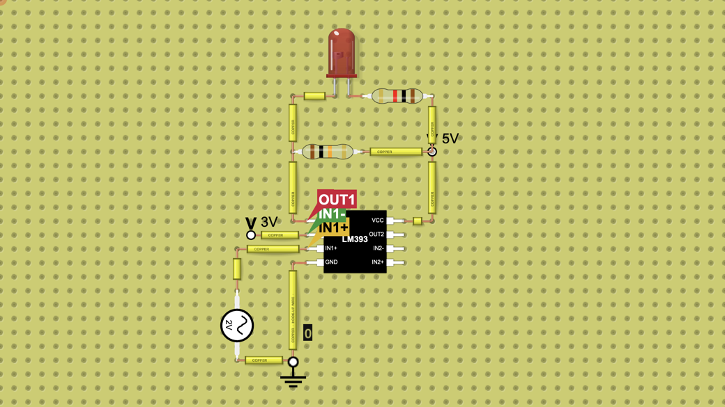
An LM393 compares a 0.5 V to 4.5 V sine with a 3 V reference. With a 10 kΩ pull-up, OUT1 is 5.0 V while the sine is above 3 V, and 0.21 V with the LED lit…
Want to build your own circuit? Start a new circuit in the circuit simulator
Teaching with circuits?
Create a classroom, give your students a circuit to build, and review what they submit. Try it free with one classroom and up to 5 students.
Try the free classroom demoHow it works
What this circuit does
The LM393 holds two comparators. Comparator 1 compares IN1+ with IN1-: when IN1+ is below IN1- its output pulls down to ground, and when IN1+ is above it lets go. The output can only pull down, so a 10 kΩ pull-up resistor to +5 V makes it go high.
A red LED with 1 kΩ runs from +5 V to OUT1, so it lights while OUT1 is low.
How it is wired
Pins down the left side, then up the right side, as the lab draws them:
Pin 1, OUT1: to the 10 kΩ pull-up (to +5 V) and to the LED cathode; the LED anode goes through 1 kΩ to +5 V.
Pin 2, IN1-: to a 3 V terminal, the reference (on a real board, two resistors from 5 V).
Pin 3, IN1+: to the sine source (2 V peak on a 2.5 V offset, 1 kHz); the source's other side goes to ground.
Pin 4, GND: to the ground part.
Pins 5 to 7, the second comparator (IN2+, IN2-, OUT2): not used.
Pin 8, VCC: to the +5 V terminal.
What the chart shows
What's inside
- 2× Battery
- 1× Power Source
- 2× Resistor (10 kΩ, 1 kΩ)
- 1× LED
- 1× LM393