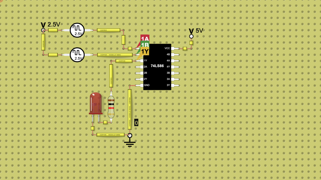
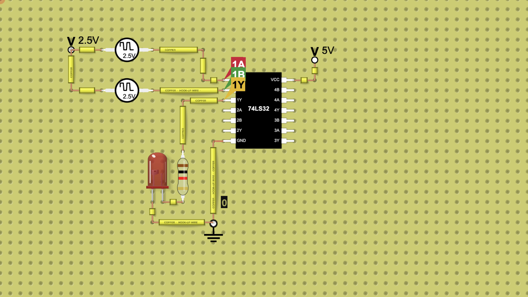
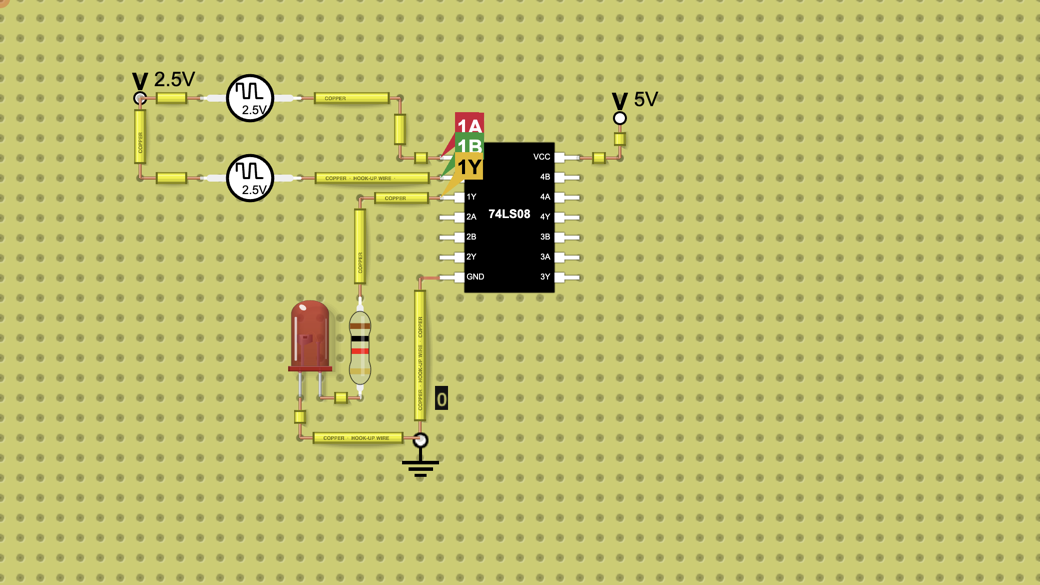
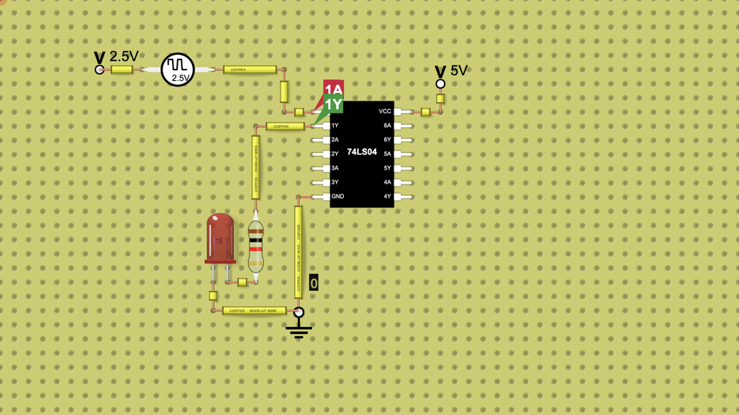
74LS02 NOR Gate Truth Table on the Chart
A 74LS02 NOR gate driven by two 0 to 5 V square waves (500 Hz and 1 kHz). The chart draws its truth table as a timing diagram: 1Y goes high only when both…
Want to build your own circuit? Start a new circuit in the circuit simulator
Teaching with circuits?
Create a classroom, give your students a circuit to build, and review what they submit. Try it free with one classroom and up to 5 students.
Try the free classroom demoHow it works
What this circuit does
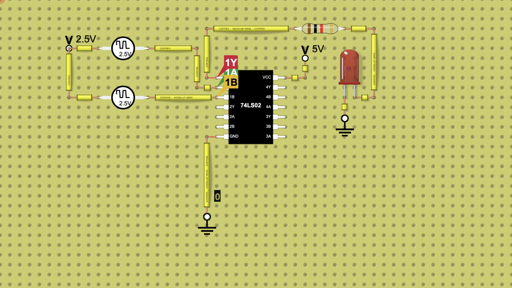
The 74LS02 holds four 2-input NOR gates. This circuit drives gate 1 with two square waves so that the chart shows every input combination one after another: a truth table drawn as a timing diagram. 1Y goes high only when both inputs are low.
The LED lights while 1Y is high.
How it is wired
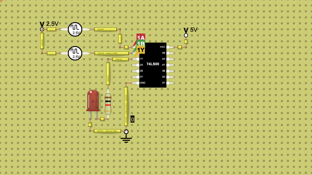
The 74LS02 is the odd one of the family: its output comes first (pin 1 is 1Y, then 1A and 1B), the reverse of the 74LS00. Pins down the left side, then up the right side:
Pin 1, 1Y: through a 1 kΩ resistor to the LED anode; the LED cathode goes to ground.
Pin 2, 1A: to square-wave source A (500 Hz).
Pin 3, 1B: to square-wave source B (1 kHz).
Pin 7, GND: to the ground part.
Pin 14, VCC: to the +5 V terminal.
The other pins (gates 2 to 4) are not used. Each input source is a ±2.5 V square wave standing on a shared 2.5 V terminal, so each input swings between 0 V and 5 V.
What the chart shows
What's inside
- 2× Battery
- 2× Power Source
- 1× Resistor (1 kΩ)
- 1× LED
- 1× 74LS02