
Car relay circuit: how an automotive relay switches a motor
- Objective
- Find out how a car relay lets a small dashboard switch control a big motor current: measure the coil current and the motor current side by side, read the terminal numbers on a car relay diagram (30, 85, 86, 87 and 87a), work out the coil's power, and see why each circuit has its own fuse, sized to the current it carries.
- Level
- High school and first-year college
- Time
- 45 minutes
- Topics
- Automotive relays, relay terminals 30, 85, 86, 87 and 87a, normally open and normally closed contacts, coil current (I = V ÷ R), power (P = V × I), stall current, fuse sizing
Steps
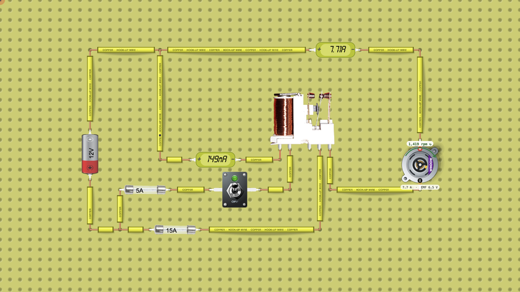
- Look at the circuit. It has two circuits sharing one 12 V battery (on the left, + at the bottom). The control circuit: a 5 A fuse at the battery feed and the dashboard switch after it, at the bottom left, feed the relay's coil, and an A meter (ammeter) sits on the coil's return wire, just left of the relay. The load circuit: the bottom wire runs from the battery through a 15 A fuse to the relay's contact, which feeds the DC motor on the right; the motor's A meter is on the top wire, back to the battery. The motor uses the Window lift preset with Load (%) 40, standing in for the window glass.
- Read the relay as you would a car relay diagram. Its five pins, left to right: the leftmost pin is 85 (wired back to the battery's negative) and the second is 86 (fed by the switch), the two ends of the coil (this coil has no diode, so either way round works); then 87a (left empty here), 30 (from the 15 A fuse) and 87 (to the motor). Terminal 30 is the common contact: at rest it touches 87a, and when the coil is energized it moves over to 87. Click the relay: Relay Type is Normally Open, Coil resistance is 80 Ω and On current is 25 mA, the coil current needed to pull the contact in.
- Run the circuit on this page; it runs without signing in. To work in the full lab instead, press Open in the lab and sign in. The switch is closed when the circuit loads, so the relay is pulled in and the motor runs. Fill in the first row of the table: the coil A meter, the motor A meter (in the motor current column) and the speed on the label above the motor. The current on the label below the motor should match the motor A meter: 7.7 A.
- Click the switch to open it: the coil current drops to zero, the relay lets go and the motor stops. Close it again and the motor restarts. After a change like this the motor's A meter can keep showing an averaged value marked RMS, so from here on read the motor current on the motor's label. The coil A meter kept the right value in our tests; if it ever shows RMS, check it with I = V ÷ R.
- Click the relay and set Coil resistance to 30 Ω (the lab's default). Record the coil current, then work out the coil's power with P = V × I. Now try 400 Ω and then 700 Ω: is the relay still pulled in, and does the motor run? Set Coil resistance back to 80 Ω.
- Click the motor and set Load (%) to 0, record the current, and set it back to 40. Then change Preset to Wiper and then to Blower, recording the speed and the current on the motor's label each time (Load stays at 40 %). Set Preset back to Window lift.
- Click the relay and set Relay Type to Normally Closed. Open and close the switch and note when the motor runs. Set Relay Type back to Normally Open.
- Fuse demo, once, and only watch it: click the motor and tick Locked rotor, as when the window glass reaches the end of its travel. The label above the motor shows STALL and the current. Watch the 15 A fuse and the coil A meter: within a few seconds (under 3 s in our runs) the fuse blows and the motor stops, but the relay stays pulled in. Reload the page to get the original circuit back.
Data table
| Setting (switch, coil Ω, preset, load %, relay type, locked) | Coil A meter (mA) | Relay pulled in? (yes or no) | Motor current (A): the motor A meter on the first row, then the motor's label | Speed (rpm) | What you saw |
|---|---|---|---|---|---|
Questions
- Compare the coil current with the motor current. How many times bigger is the motor current? Why can the dashboard switch and its wire be small and thin, and why does that wire get its own 5 A fuse instead of sharing the 15 A one?
- Work out the coil current and the coil's power with I = V ÷ R and P = V × I for an 80 Ω coil and for a 30 Ω coil, and compare them with your readings. Why does a car relay use a coil of about 80 Ω rather than 30 Ω?
- Did the relay pull in at 400 Ω and at 700 Ω? Use the On current of 25 mA to explain why.
- With the rotor locked, what current did you read? Work it out from the Window lift preset (12 V, 18 A stall current). Why did the fuse blow, and why did the relay stay pulled in?
- The Wiper preset stalls at 12 A. Predict, without trying it, what the 15 A fuse would do if a Wiper motor locked in this circuit. What fuse rating would protect it?
- With Relay Type set to Normally Closed, which car relay terminal was the motor behaving as if it were wired to? A real power window must go up and down: how can two relays, each with 30, 87 and 87a, reverse the motor?
For teachers
Answer key
- Measured: the coil A meter read 149 mA and the motor A meter 7.71 A, so the motor current is about 52 times the coil current (7.71 A ÷ 0.149 A). Computed from the Window lift preset: 5 % of the 18 A stall current to keep it turning (0.9 A) plus 40 % of the rest, 0.9 A + 0.4 × 17.1 A = 7.74 A; with Load (%) 0 the motor's label showed 0.9 A. The switch and its wire only carry the coil current, about 0.15 A, while the 7.7 A flows on the short path from the fused battery feed through 30 and 87 to the motor. So the wire behind the dashboard can be thin, it wastes little voltage over its length, and the switch contacts do not burn from a big current. The 5 A fuse is there for the thin wire: a fuse protects the wire after it, so it must blow before that wire overheats. That is why it sits right where the control circuit leaves the battery feed, before the switch. 5 A is far above the 0.15 A coil current, so it never blows in normal use, but a short to ground in the thin switch wire would blow it. A dead short would blow even the 15 A fuse at once; the 5 A fuse matters for smaller faults, such as a partial short or a faulty part drawing 5 to 15 A, which the 15 A fuse would let through while the thin wire overheats. A fuse rating follows the wire it protects. Real cars fuse the switch side too, with a fuse sized for its own wiring.
- Computed at 80 Ω: I = 12 V ÷ 80 Ω = 0.15 A (150 mA) and P = 12 V × 0.15 A = 1.8 W; measured 149 mA. At 30 Ω: I = 12 V ÷ 30 Ω = 0.4 A and P = 12 V × 0.4 A = 4.8 W; measured 397 mA. Both coils pull the relay in, but the 30 Ω coil turns more than two and a half times as much power into heat and puts more current through the switch for no benefit: 150 mA is still six times the 25 mA On current. That is why 12 V car relays use coils of roughly this size, around 1.5 to 2 W.
- Measured: at 400 Ω the coil current was 29.8 mA (computed 12 V ÷ 400 Ω = 30 mA), above the 25 mA On current, so the relay pulled in and the motor ran. At 700 Ω it was 17.1 mA (computed 12 V ÷ 700 Ω = 17.1 mA), well below it, so the relay stayed at rest (30 on 87a) and the motor did not run even with the switch closed. The lab's relay pulls in once the coil current reaches about its On current (just under 25 mA in the model) and falls back to rest below about 19.5 mA; in between, the contact hangs half-way and touches neither 87 nor 87a. In a real car, a weak battery or a bad ground on 85 can lower the coil current the same way, and the relay does not click.
- Locked, the motor has no back-EMF, so I = V ÷ R. From the motor's settings: R = 12 V ÷ 18 A = 0.667 Ω, so I = 12 V ÷ 0.667 Ω = 18 A, the preset's stall current (computed). The lab measured 16.74 A, and the label above the motor showed STALL 17 A. The reading is a little lower because the motor is not alone in the loop: three small resistances you cannot read in the lab, the battery's internal resistance (0.01 Ω), the 15 A fuse (0.01 Ω) and the relay's closed contact (0.03 Ω), add 0.05 Ω, and 12 V ÷ 0.717 Ω = 16.7 A. That is above the fuse's 15 A rating, so the fuse blew within a few seconds (under 3 s in our runs: the simulator starts a 1 to 2 s countdown when it sees the overload and can restart it while the current is still changing) and stopped the motor before its winding (about 187 W of heat, P = I² × R) overheated. The coil A meter dipped from 149 mA to 147.9 mA during the stall, because the battery's voltage sags a little under 16.7 A, and read 150 mA once the fuse had blown and no motor current flowed. The coil is a separate circuit, so the relay stays pulled in; it just has nothing to switch. The simulator's fuse is idealized and blows within seconds of any overload; a real fuse carries a short overload longer, so a window motor that stalls for a moment at the end of its travel does not blow it.
- Computed: the Wiper's winding is R = 12 V ÷ 12 A = 1.0 Ω, so locked it would draw about 12 A, its preset stall current; in this circuit a little less, about 12 V ÷ 1.05 Ω = 11.4 A, for the same reason as in question 4. That is below 15 A, so the fuse would not blow, and the winding would overheat and could burn out. A fuse protects only if its rating is above the running current and well below the stall current: the Wiper's label showed 5.2 A at 868 rpm with Load 40 %, so a 7.5 A fuse. A 10 A fuse would leave too little margin under its 12 A stall current. The Blower stalls at 25 A (preset; about 12 V ÷ (0.48 + 0.05) Ω ≈ 22.6 A in this circuit), above 15 A, so the 15 A fuse does protect it; what needs the larger fuse is its running current, 10.7 A on its label at 1944 rpm. Real motors often also have a built-in thermal cutout.
- Normally Closed made the motor run with the switch open and stop when it was closed, as if the motor were wired to 87a, which touches 30 at rest. A real power window uses two relays: each end of the motor goes to terminal 30 of its own relay, both 87a terminals go to ground and both 87 terminals go to the fused 12 V feed. At rest both ends of the motor are grounded and it stays still. Energize the up relay and one end goes to 12 V, so the motor turns one way; energize the down relay instead and the other end goes to 12 V, so it turns the other way. This lab's relay has 87a, so you can build it, but it doubles the parts; to see a motor reverse, try the DC motor activity.
Frequently asked questions
Do students need an account?
Not to run the circuit on this page: it runs in the browser without signing in. To work in the full lab (Open in the lab), students sign in, and free accounts have a time limit there. Saving their own copy needs a DCACLab plan. To hand the work in as an assignment, they join your class through its join link.
Do I need a real car or real parts?
No. The relay, the fuses, the switch and the 12 V motor are all simulated with realistic car values, so there is nothing to buy and a blown fuse costs nothing. The lab runs in a web browser, so students can also do this at home. The circuit on this page runs without signing in; to work in the full lab (Open in the lab), they sign in, and free accounts have a time limit there.
What do 30, 85, 86, 87 and 87a mean on a car relay diagram?
They are the standard terminal numbers printed on most car relays. 85 and 86 are the two ends of the coil: 86 usually gets the switched 12 V and 85 goes to ground. 30 is the common contact, usually the fused feed from the battery. 87 is the normally open contact: it connects to 30 only while the coil is energized. 87a is the normally closed contact: it connects to 30 at rest. A four-pin relay has no 87a. If the relay has a diode across its coil, 86 must be the positive side. The lab's relay has all five pins, left to right: the two coil pins, 87a, 30 and 87.
More in the virtual lab: Virtual physics lab for circuits and electronics
Teaching with circuits?
Create a classroom, give your students this lab, and review what they submit. The free classroom demo gives you one classroom with room for 30 students for 7 days, counted from when your first student joins (once per teacher); after that it keeps up to 5 students.
Try the free classroom demo