7805 Regulator: Bridge Rectifier to a Steady 5 V
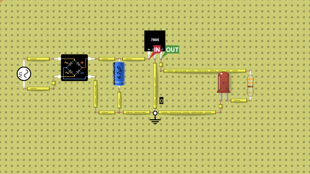
AC, a bridge rectifier and a 4.7 µF capacitor feed a 7805 wired IN, GND, OUT left to right. IN ripples between 9.3 V and 10.5 V while OUT holds a steady…
Want to build your own circuit? Start a new circuit in the circuit simulator
Teaching with circuits?
Create a classroom, give your students a circuit to build, and review what they submit. Try it free with one classroom and up to 5 students.
Try the free classroom demoHow it works
What this circuit does
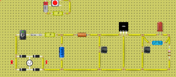
The 7805 turns a higher, unsteady DC voltage into a steady 5 V. Here a 12 V peak, 1 kHz AC source goes through a bridge rectifier, a 4.7 µF capacitor smooths the bumps, and the 7805 removes the ripple that is left. Its 5 V output lights a red LED through 330 Ω.
How it is wired
Pins left to right, as the lab draws them:
Pin 1, IN: to the bridge rectifier + terminal and the capacitor + side.
Pin 2, GND: to the bridge rectifier - terminal, the capacitor - side, the LED cathode and the ground part.
Pin 3, OUT: through 330 Ω to the LED anode.
The AC source connects to the two ~ terminals of the bridge rectifier. The middle pin is GND, not the output.
What the chart shows
Switch the lab on and the chart draws the ticked boxes; you do not need to tick anything.
Ticked: IN and OUT. The chart covers the first 5 ms. IN starts at 0 V, charges to 10.5 V in the first quarter cycle, then ripples between 9.3 V and 10.5 V, dipping twice per AC cycle (every 0.5 ms) as the capacitor feeds the load between peaks.
OUT follows IN, 2 V lower, until IN passes 7 V, then holds 5.00 V flat through all the ripple. The LED carries 9 mA.
What's inside
- 1× Power Source
- 1× Resistor (330 Ω)
- 1× Capacitor
- 1× LED
- 1× Bridge Rectifier
- 1× 7805