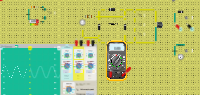
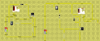
Battery Polarity Test Circuit
Battery Polarity Test: This diagram shows a basic battery tester circuit that uses two LEDs and four 1N5399 diodes to visually indicate the polarity and…
¿Enseñas con circuitos?
Crea un grupo, deja un circuito a tus alumnos y revisa lo que entregan.
Ver planes para maestrosCómo funciona
Battery Polarity Test:
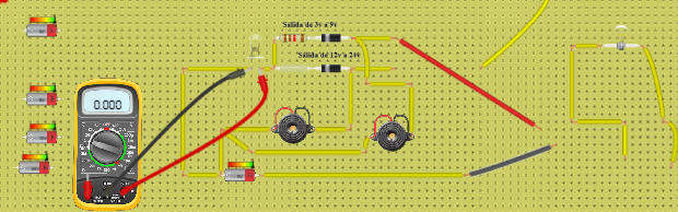
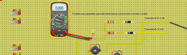
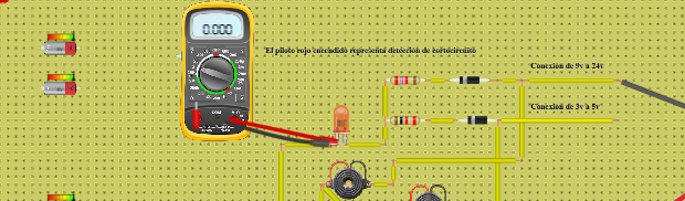
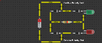
This diagram shows a basic battery tester circuit that uses two LEDs and four 1N5399 diodes to visually indicate the polarity and status of a connected DC battery. Each LED is paired with two diodes in series to direct the current flow, and a 1kΩ resistor limits the current through both paths.
When the battery is connected with the correct polarity, the green LED turns on, indicating proper voltage and polarity.
If the battery is connected in reverse, the red LED lights up instead. This simple and efficient design is well-suited for quick polarity testing and basic voltage detection in DIY projects and educational electronics.
Qué contiene
- 1× batería
- 1× resistencia (1 kΩ)
- 2× LED
- 4× diodo