P-Channel MOSFET circuit using buzzer
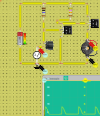
The schematic for the P-Channel MOSFET circuit we will build is shown below, So, this is the setup for pretty much any P-Channel MOSFET Circuit. Negative…
Teaching with circuits?
Create a classroom, give your students a circuit to build, and review what they submit.
See classroom plansHow it works
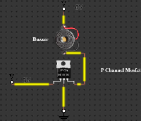
The schematic for the P-Channel MOSFET circuit
we will build is shown below,
So, this is the setup for pretty much any P-Channel MOSFET Circuit.
Negative voltage is fed into the gate terminal. For an IRF9640 MOSFET, -3V at the gate is more than sufficient to switch the MOSFET on so that it conducts across from the source to the drain. Now that we have hooked up sufficient voltage to the gate to turn on the transistor, then we must supply voltage to our load on the source terminal of the transistor. Remember, one voltage is to turn on the transistor and the other voltage is to power the load once the transistor has been turned on.
The amount of voltage that needs to be connected to the load depends entirely on how much voltage the load needs to be powered on. If you are using a 6V DC motor or buzzer, then you connect 6V to the source terminal. If you are powering a 12V motor or buzzer, then you connect 12V.
Since the buzzer we are using in this circuit requires 6V, 6V is connected to the source terminal.
So P-Channel MOSFET is set up and works.
What's inside
- 2× Battery
- 1× Transistor
- 1× Buzzer