RC Low-Pass Filter: Frequency Response Lab
A 1.6 kΩ resistor and a 1 µF capacitor make an RC low-pass filter with a 99.5 Hz cutoff. Run an AC sweep from 1 Hz to 10 kHz and read gain and phase.
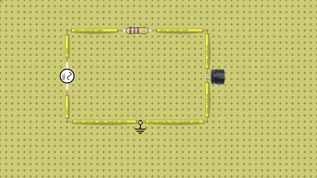
Usa este circuito con tu grupo: Filtro RC pasa bajas: frecuencia de corte y barrido de CA
¿Enseñas con circuitos?
Crea un grupo, deja un circuito a tus alumnos y revisa lo que entregan. Pruébalo gratis con un grupo y hasta 5 alumnos.
Prueba gratis la demo para maestrosCómo funciona
A resistor in series and a capacitor to ground pass slow signals and block fast ones. The cutoff frequency is fc = 1/(2πRC): with 1.6 kΩ and 1 µF it is 99.5 Hz, where the output is 0.707 of the input and lags it by 45°.
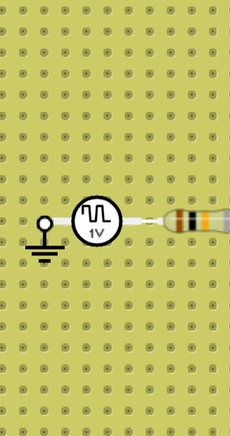
The source is a 10 V peak, 100 Hz sine wave. In the full lab, the NGSpice AC Sweep chart plots the output (N2) in volts and its phase in degrees from 1 Hz to 10 kHz, and the Time Domain chart shows the smaller, delayed output wave.
Qué contiene
- 1× fuente de alimentación
- 1× resistencia (1.6 kΩ)
- 1× capacitor