LM317 Adjustable Regulator Set to 5 V
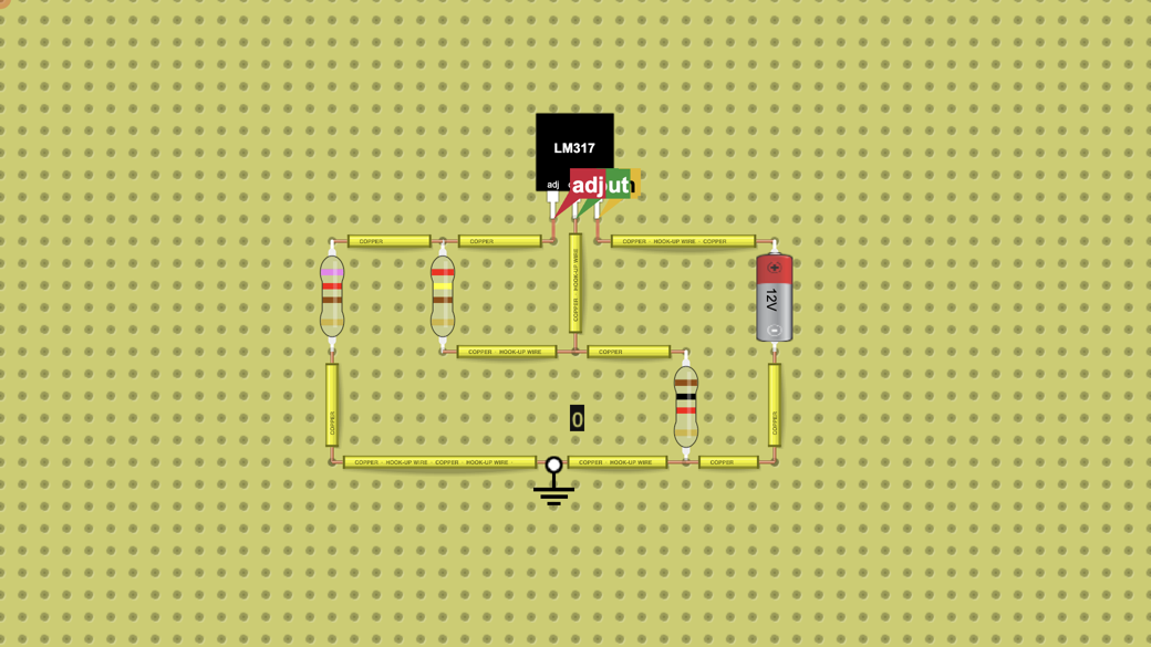
A 12 V battery feeds an LM317 wired adj, out, in left to right. 240 Ω and 720 Ω set the output: out reads 5.04 V and adj 3.79 V, always 1.25 V below out.…
Mengajar dengan rangkaian?
Buat kelas, beri siswa rangkaian untuk dirakit, dan periksa hasil kiriman mereka. Coba gratis dengan satu kelas dan hingga 5 siswa.
Coba demo kelas gratisHow it works
What this circuit does
The LM317 is an adjustable regulator: it keeps out 1.25 V above adj, and two resistors choose the output voltage. With R1 = 240 Ω from out to adj and R2 = 720 Ω from adj to ground, out = 1.25 V × (1 + R2 / R1) + 50 µA × R2 = 5.04 V. A 1 kΩ load draws 5 mA.
How it is wired
Pins left to right, as the lab draws them (the order is not the same as the 7805):
Pin 1, adj: to the point between R1 (240 Ω, to out) and R2 (720 Ω, to ground).
Pin 2, out: to R1 and to the 1 kΩ load; the other end of the load goes to ground.
Pin 3, in: to the battery + terminal (12 V). The battery - terminal goes to ground.
The pin on the right is the input. Wire the supply to the left pin, as on a 7805, and out stays at 0 V.
What the chart shows
Switch the lab on and the chart draws the ticked boxes; you do not need to tick anything.
Ticked: in, out and adj. The chart covers 5 ms. in is a flat 12.0 V, out settles at 5.04 V and adj at 3.79 V, 1.25 V below out.
Try this
What's inside
- 1× Battery
- 3× Resistor (240 Ω, 720 Ω, 1 kΩ)
- 1× Adjustable Regulator