Build a simple circuit using a battery diode resistor and led
Here’s a basic LED circuit using a battery, a diode, a resistor, and an LED:
Components:
- 1 × Battery (e.g., 6V)
- 1 × Resistor (e.g., 330Ω to 1kΩ)
- 1 × LED (any color)
- 1 × Diode (e.g., 1N4001)
How it works:
- The resistor limits the current so the LED doesn’t burn out.
- The diode protects the LED from reverse polarity by blocking reverse current.
- When connected correctly (battery + to LED anode), the LED lights up.
- If the battery is reversed, the diode blocks the current and the LED stays off protecting it.
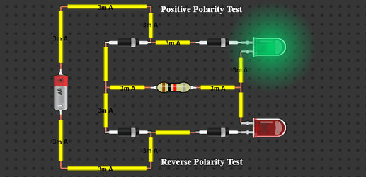
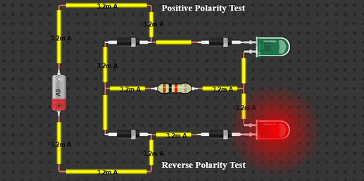
Example: Battery Polarity Test Circuit
-
Green LED (Correct Polarity):
- Turns on when the battery is connected with the correct polarity.
- The current flows through two 1N5399 diodes and the green LED.
- A 1kΩ resistor limits the current to protect the components.
-
Red LED (Reverse Polarity):
- Lights up if the battery is connected in reverse.
- The current takes an alternate path through two other diodes and the red LED.
- The same 1kΩ resistor is used to limit current in both cases.
This setup gives you a simple way to test battery polarity with just a glance - green means correct, red means reversed.

