Лаборатория

smart home pcb fan

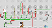
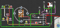
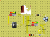
An interactive resistor, capacitor, battery and switch circuit built in the DCACLab online simulator by Sunil Vaishya.
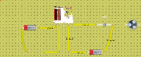
Preview of smart home pcb fan
Open in the lab Embed Run the circuit right here. To edit it in the full lab, sign in; free accounts have a time limit there.

Преподавате с вериги?

Създайте клас, дайте на учениците си схема за сглобяване и прегледайте предадените работи. Опитайте безплатно с един клас и до 5 ученици.

Изпробвайте безплатната демо версия за клас

What's inside

  • 2× Battery
  • 2× Resistor (1 Ω, 999 mΩ)
  • 1× Capacitor
  • 1× Switch
  • 1× Relay
  • 1× Fan

Tags

About

By Sunil Vaishya
Saved August 06, 2024 · updated January 15, 2026
1,389 views
Page: dcaclab.com/circuits/75804-smart-home-pcb-light

Embed this circuit

<iframe src="https://dcaclab.com/experiments/75804-smart-home-pcb-light/iframe" width="560" height="410" frameborder="0"></iframe>

Cite: Vaishya, S. (2024). smart home pcb fan. DCACLab. https://dcaclab.com/circuits/75804-smart-home-pcb-light

Related circuits