MAKING A CIRCUIT USING A RELAY
- INTRODUCTION
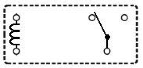
An electromagnetic relay in its switching principle is a mechanical switch which is operated with a low-power DC voltage. The switch part is used to control high power circuits. - SPDT RelayRelay design
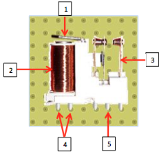 The SPDT relay is mainly made up of :1. Movable armature
2. Control coil
3. Switch contact points
4. Coil terminals
5. Common terminalDescription
RELAY SPDT (single pole double throw) has a total of five terminals Out of these two are the coil terminals. A common terminal is also included which connects to either of two others. When a voltage is applied to the control circuit, the coil traversed by a current will create an electromagnetic field; this latter is capable of moving a metal element called movable armature.
- Experimentation*.Objective:
Make circuit by using a relay in the DCAClab simulator.*. Equipment:- Battery (Electromotive Force E = 1.5 v , Internal resistance r = 1 Ω)
- Switch K1
- Coil (r1 = 1Ω)
- Relay Switch
- Lamp (r2 = 1Ω)
- Fan
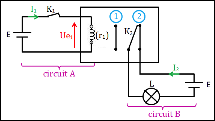
*. Experiment 1: order a single circuit
- Experimental mounting
- Interpretation
- Level 1
1st case: Relay at rest
The switch K1 open ( I1 = 0 ) ⇒K2 at the position (1), consequently the circuit B is open : I2 = O , so the lamp L is off .
2nd case: Relay at work
The switch K1 is closed ( I1 ≠ 0 )⇒K2 at the position (2), consequently the circuit B is close : I2 ≠ 0 , so the lamp L is on . - Level 2_ calculating the intensity of the current I1:Ohm’s law: Ue1 = r1 I1 = E – r I1
So I1 = E/ (r1 + r) = 0.04838A ≈ 48.38 mA_ calculating the power P1:
P1 = E I1 = 1.5 x 0.04838 = 0.07257 w
_ Value of the intensity I2:
By using the characteristics of the lamp we find I2 = 1.456 A
_ calculating the power P2:
P2 = E I2 = 1.5 x 1.456 = 2.184 w
Conclusion:
The relay can be used to control a high power circuit by a low power circuit.
- Level 1
- Experimental verification using the DCAClab simulator
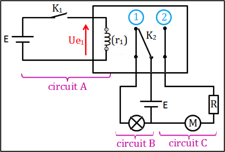
*. Experiment 2 : order 2 circuits
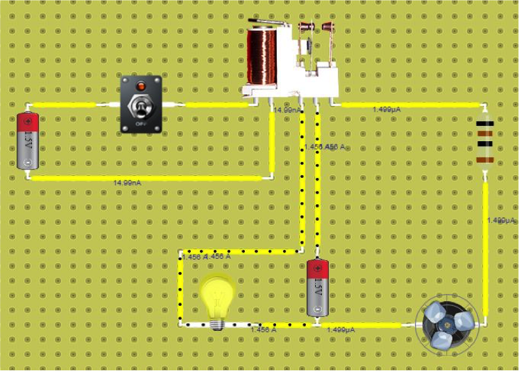
- Experimental mounting1st case: Relay at restThe switch K1 is open ⇒K2 at the position (1), consequently:
- The circuit B is closed, so the lamp is on.
- The circuit C is open, so the fan is off.
- Experimental verification using the DCAClab simulator
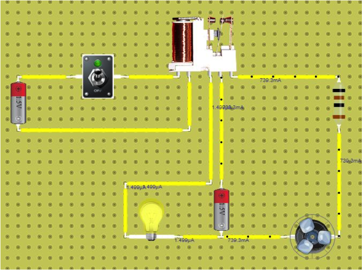
2nd case : Relay at workThe switch K1 is closed⇒K2 at the position (2) , consequently :- The circuit B is open, so the lamp is off.
- The circuit C is closed, so the fan is on.
- Experimental verification using the DCAClab simulator
the end.
5 Replies to “MAKING A CIRCUIT USING A RELAY”
Its nice to play with it. The UI makes me feel like i’m using an actual Relay unit in a lab.
Keep up the great work guyz.
Hello! Do you use Twitter? I’d like to follow you
if that would be okay. I’m definitely enjoying your blog
and look forward to new posts.
Hi 🙂 Yes, we use Twitter, our account is @DCACLab , next release will have an improved Oscilloscope, we will be tweeting about once its released!